Derby Talk is a forum for Pinewood Derby, Awana Grand Prix, Kub Kar Rally, Shape N Race Derby, Space Derby, Raingutter Regatta and other similar races where a child and an adult work together to create a race vehicle and a lot of fun and memories
whodathunkit wrote:Hello, all! This is my first post (reply) on Derby Talk. This particular axle drill jig that you're talking about was made by Superior Tool. Their website is http://www.superior-tool.com" target="_blank
I thought that I had seen that on some other website.
That website indicates that it is made out of steel, but the PinePro listing on eBay says aluminum. Hmm
gpraceman wrote:
According to this eBay listing, it is aluminum.
For ~16 USD, aluminum. For ~160 USD, A2 steel. But then, you'd never have to replace it, and all your friends could use it.
I've often heard people brag about their Pack's line-up of Engineer Dad's...but me thinks the ones to look out for are the professional machinists, or those with easy access to a machinist who has a well stocked "cage."
Kenny wrote:I've often heard people brag about their Pack's line-up of Engineer Dad's...but me thinks the ones to look out for are the professional machinists, or those with easy access to a machinist who has a well stocked "cage."
That is a neat aspect of being an ME at Cat! Many have the shop background for themselves, ongoing access to the machines, and loads of shop contacts! If lucky enough to work in Cat's Development Center, all those factors are greatly increased!
Stan
"If it's not for the boys, it's for the birds!"
I have this tool and gave it a try recently. As others have mentioned, it is for drilling axle holes when you don't have a drill press. It is somewhat comparable to the Pro Body Tool/Pro Body Jig made by DerbyWorx. The main differences are that this tool allows you to adjust two set screws in order to manipulate the degree of camber you are providing (positive and negative depending on tool orientation to the block) and this tool must be clamped adjacent to your block edge - as opposed to your block being clamped into the tool for the DerbyWorx tools. This makes you a little more aware of how flat the surface is that you are clamping the tool and (potentially) your block to. While all three of these commonly available tools are made of aluminum, the drill guide on this tool is about twice as long as found on the Derby Worx tools (which is nice).
The other main thing worth noting is that this tool has a fixed hole height of 3/32" above the bottom of the block. This compares to the original Pro Body Tool. It is fine for drilling or re-drilling into the slots, or drilling clean holes with ballast below the block bottom, but not near as attractive as the ~ 11/64" hole height of the Pro Body Jig, which appears near ideal for inserting weight into your block and still providing 3/8" center guide clearance for inspection.
Here are my observations from using the tool:
- Firsrt off, the provided drill bit is too short for completely drilling the axle hole, you will have to 'finish up' without the tool or use a longer drill bit;
- Drilling straight axle holes (at the 3/32" height) went pretty well. I think a fresh tool can give you drilled holes that are straight enough for being competitive in most Packs;
- Even drilling straight holes though, you need to place the tool at the edge of your table so that you have access with your drill bit holder;
- When trying to set up the tool for cambered holes, I found it a bit difficult getting the set screws at a perfectly equal height to avoid any unwanted toe. Eventually I resorted to putting the tool on an inspection plate and using a piece of paper to just barely get the 2nd screw down to the surface after adjusting the other screw first.
- It also was a bit more difficult to clamp the tool for negative cambered rear holes because you have the raised edge outward and a lowered edge facing the block - so you have to get a clamp in between the two "just right". This was less of an issue for positive cambered holes because the angle was 'in your favor' for clamping.
- The camber adjustment will typically only be useful on one axle at a time since you likely don't want your fore/aft axles at the same angle.
So I would conclude that this is a nice, but limited in application tool. The 3/32" drill height and difficulty getting the same height on both set screws (they are a little "touchy") are real killers. You could use two 1/16" feeler gauges (one under each screw), but I did not try that and it would still be a hair lower than the ProBody Jig. I think a very lightly used tool can do a darn good job drilling low, straight holes, especially if you have a very flat surface to clamp it all to. The camber adjustment that is probably its main attraction comes with some additional headaches and concerns. I suspect it would have a little longer life than my ProBody Jig since the drill guide depth is measurably longer. (After 1 1/2 seasons and a fair bit of use my ProBody Jig has overly large drill guide holes and I won't use it any more.)
If you want straight holes all around though, I don't see any significant advantage over the ProBody Jig unless you are happy with the hole height and the $13 is that important to you. If you found the original, hardened steel version of this tool, then you have likely spent much more. If you want cambered holes, at a custom height and angle, I will take my variable angle plate any day. By the way, the plate I have now is 1 13/16" wide, which offers better holding ability and overcomes some of the concern listed above. It obviously does require a drill press though and has its own issues which you have to live with. The perfect for all, low cost tool, will likely never be found !
Yes, I'm dragging this up from the past, as I just bought one of these to try canted axle holes instead of bending the axles. Did anyone figure out how far to extend the set screws to get 2.5º of camber similar to what the Rail Rider Tool bends axles to?
I bought one of these but haven't used it yet. I plan to use a micrometer to set the screws to the same height. I'll bend a axle at 2.5 degrees with my DerbyWork ProBody/RR tool. I'll insert that into a straight hole right up to the bend point. I'll then drill canted holes with the Superior jig and insert perfectly straight axles or another bit. I'll keep adjusting the screws and drilling holes until the straight axle or bit in the canted hole matches the prebent axle. I'll then take a reading with the mic and put some threadlocker on the threads so the don't move.
I've got my tool dialed in. As Quadad says, it seems nearly impossible to get the two screws set to the same height when measured individually. The reason is that the bottoms of the screws aren't perfectly flat all the way across. This also means that the tool has to be resting on a perfectly smooth/hard surface.
To get them the same height I turned the tool upside down (bottom of screws facing up) with the screws where I think they look the same. Next, I placed a piece of sheetmetal across the screws. The edge of the sheetmetal is then held flush with the edge of the tool with tape. Now measure with a caliper from the bottom of the tool to the top of the sheetmetal. Take this measurement in line with the screws so it's accurate. Hold the caliper so the fixed end rests flat on the sheetmetal and bring the moveable portion of the caliper up to the bottom of the tool until it just makes contact. This is the reading you want to be equal at both screws. If the fixed portion of the caliper is not exactly flat on the top of the sheetmetal then the reading will fluctuate. This is extremely accurate from screw to screw because the bottom side of the tool (which is the top when turned right side up) will have the 2 slots in it that are used to line it up with your pencil marks on a block where the axles will go. The knife edge on the caliper surface will lay right in that slot on the bottom. As long as the top/fixed part of the caliper is perfectly flat on the top of the sheetmetal you will be accurate. I'm able to repeatedly measure mine and have less than .001" difference each time from screw to screw. Once they were equal I put a dab of red locktite on both sides of the screw so they won't move. You could also place blue locktite or Elmers glue on the threads before even adjusting them. By the time you get it adjusted the locktite will be secure. If they need to be moved again later then they will still turn but will have resistance and stay in position.
To drill the holes:
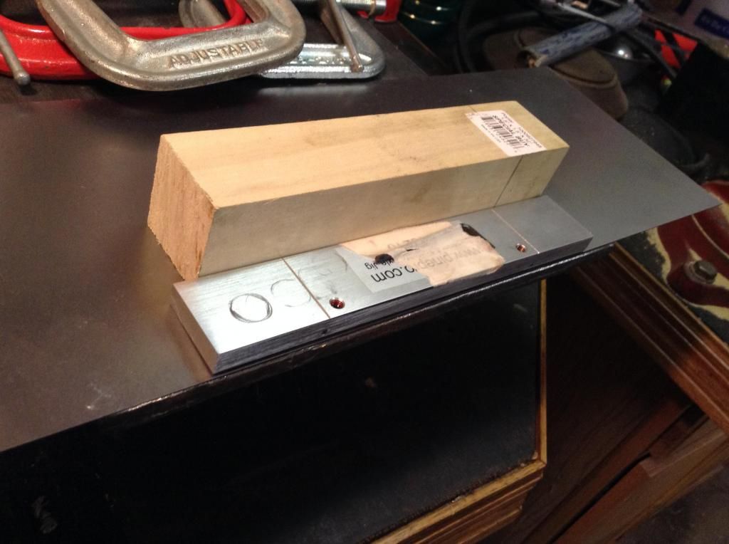
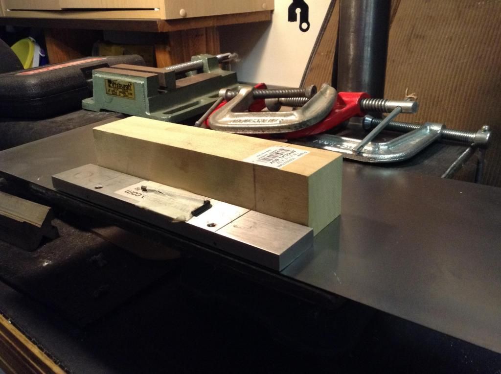
1) I clamped a piece of thin sheetmetal to my drillpress table with the edge of the sheetmetal flush with the front edge on the table. You could use any flat table with an edge like a kitchen countertop . This sheetmetal has to be big enough for both the tool and the block to fit. Unless you want to have the holes slightly higher on the block then make the sheetmetal just big enough for the screws to get on it. This way the block will be slightly lower (the thickness of the sheetmetal). I noticed when drilled with both tool and block at same height that the pointed/inward tip of the axle is very slightly within the confines of the block of wood. Meaning, the axle is angled downward with the point very close to the surface of the wood. Doesn't look like a problem but as Quadad says, maybe some will want to raise the hole slightly.
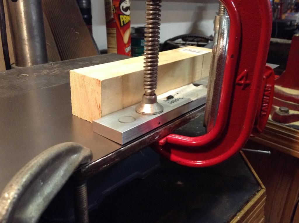
2) Next I clamp the tool to the sheetmetal with edge of the tool flush with the front edge of the table and sheetmetal. I use simple C-clamps and place them over the screws to prevent the tool from bending. Not much pressure is needed to hold the tool in place.
3) I then slide the block up against the back edge of the tool and line up the marks/grooves on the tool with my pencil marks on the block where I want the holes to be.
4) While holding the block down and pulling it up against the tool with my left hand I drill the hole with my cordless hand drill in the other hand.
5) Face the block the other direction and drill the other side using the other hole.
6) Place a known straight axle in the hole the same depth as it would be if there was a wheel on it.
7) Bend an axle to the desired angle just like you used to do. Drill a straight hole about 1/2" on either side of your angled hole and insert your bent axle with TDC of course pointing at 12:00. Now, eyeball the 2 axles and see if they appear to be at the same angle. You can check this by laying the block on a perfectly level surface. Lay a drill bit across the top of the 2 axles and tilt the block slightly so the bit rolls up against the heads of the 2 axles. Check again that the block is level after tilting. Now, check the drill bit to see if it's also level. If it is then both are at equal angles.
I hope this helps and doesn't confuse you more. It did take me quite a while to figure out how to get accurate measurements from screw to screw and this works well. Now I think I could setup another tool pretty quickly.
No problem. You do not use a drill press. I used the table on my press because it's easy to clamp everything to.
If you look in the pics you'll see on top of the tool the small setscrews. Now look right next to the screws but on the front face of the tool (opposite the block). You'll see the 2 small holes that you drill through and into the block on the other side. You can also see by looking at the end of the tool that the front face of the tool (opposite the block) is raised slightly off the table surface. This gives the canted hole. I use my cordless drill to drill through the small hole in the front face of the tool and into the block on the other side.
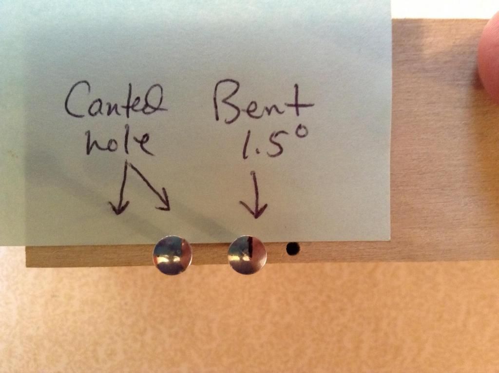
Here's a pic of axle bent 1.5 degrees in a straight hole and next to it straight axle in a canted hole drilled with the tool.
So, with a tool like this, eventually you'll wear through the holes, due to the drill bits cutting into the aluminum, I'd assume? Similar problem to the Pro-body tool/jig?
davet wrote:No problem. You do not use a drill press. I used the table on my press because it's easy to clamp everything to.
If you look in the pics you'll see on top of the tool the small setscrews. Now look right next to the screws but on the front face of the tool (opposite the block). You'll see the 2 small holes that you drill through and into the block on the other side. You can also see by looking at the end of the tool that the front face of the tool (opposite the block) is raised slightly off the table surface. This gives the canted hole. I use my cordless drill to drill through the small hole in the front face of the tool and into the block on the other side.
If you put the supplied drill bit into your hand drill just enough for it to grab solidly the bit is long enough to drill through the block and far enough into the block of wood.
Vitamin K wrote:So, with a tool like this, eventually you'll wear through the holes, due to the drill bits cutting into the aluminum, I'd assume? Similar problem to the Pro-body tool/jig?
davet wrote:No problem. You do not use a drill press. I used the table on my press because it's easy to clamp everything to.
If you look in the pics you'll see on top of the tool the small setscrews. Now look right next to the screws but on the front face of the tool (opposite the block). You'll see the 2 small holes that you drill through and into the block on the other side. You can also see by looking at the end of the tool that the front face of the tool (opposite the block) is raised slightly off the table surface. This gives the canted hole. I use my cordless drill to drill through the small hole in the front face of the tool and into the block on the other side.
I suppose that could happen. We only run scout races and this is our last year. Our Probody tool is still good after 4 years. For someone without a drill press who wants to spend less than 1/2 the cost of The Block and special bit and will only be building a scouts career worth of cars this seems like a good tool to me.
That said, I have not drilled 3 holes into an actual derby block yet and checked to see how straight it runs. I've just checked how this works with measuring tools so far. I may start running in a league here locally and if I do I'll probably invest in a Block and the special bit to go with it.