
Gents
I've been reading other threads on COG. I came across a comment by Shawn Stembleton in regards to weight placement.
Mr. Stembleton says: "For the Best Track profile, you want the weight compressed front-to-back in as little area as possible. It has to do with rotational inertia of the entire car as it transitions from the slope to the flat. If you can get the car hollowed out (routed or otherwise) everywhere underneath, except for the axle area, and put weight in a very compact form around the rear axle so that the center of mass (CoM) of the car is in that 5/8 - 7/8 of an inch range in front of the rear axle, then you will be doing well. The car will have a lower "moment arm" (I think that's the term--it's how far away from the axle the effective center of the weight rotates about that axle) and use less energy for the rotation, leaving more for speed.
My boys understand the concept well. The last 3 years we've put 4+ ounces of tungsten and a bit of lead tape completely within the space between the rear wheels. The front edge of the weight is just behind the front edge of the rear wheels, and the back is a good bit in front of the rear edge. It sits taller, but has the effect of shooting out of the curve at the bottom. The emcee of the district race used comments like "the car is pulling away on the straight," indicating that it is going faster coming out of the curve and/or slowing down less. This is in spite of being even or just behind when entering the curve. We also "dog-trot" or "crab" our cars, as you can read elsewhere."
So I'm curios now. The weight if front of my rear axle sits no further than an 1/8th if front of the rear wheel. In the back I have 5 1/4 cube tungsten that sits all the way on the very back end of the car. My thought is that I want this weight as far back as I can to give me that extra push. But this guy is saying that its best to have all your weight within the space of your rear wheel.
I also read that its better to have your weights as close to the bottom of your car (which is the way I have mine). But if I try to do it the way Mr. Stembleton suggest, then it can't be done without stacking weights.
So the question is, am I better off the way I have it (the weights behind the rear axle all the way to the back) or should I move these closer to the axle as this guy suggest?
Weight Placement
-
Stan Pope

- Pine Head Legend

- Posts: 6856
- Joined: Sat Jul 05, 2003 7:01 pm
- Location: Morton, Illinois
- Contact:
Re: Weight Placement
From your description, I can't tell the distribution of your cubes. Also, what is your CM location? Please give details.
We have done several cars with 6X2X1 arrays nestled against the 1/4" wide strip that houses the rear axles, which I think is the configuration that Shawn was suggesting. Perhaps he was suggesting that the front array be slightly more forward, as this location leaves the DFW weight pretty light.
We have done several cars with 6X2X1 arrays nestled against the 1/4" wide strip that houses the rear axles, which I think is the configuration that Shawn was suggesting. Perhaps he was suggesting that the front array be slightly more forward, as this location leaves the DFW weight pretty light.
Stan
"If it's not for the boys, it's for the birds!"
"If it's not for the boys, it's for the birds!"
-
Stan Pope
- Pine Head Legend
- Posts: 6856
- Joined: Sat Jul 05, 2003 7:01 pm
- Location: Morton, Illinois
- Contact:
Re: Weight Placement
Remember, too, that on the straight ramp of a Best Track moving the CM rearward does not give advantage. The advantage from more rearward location of the CM happens in the curved section, where you are reporting you're gaining advantage!
Stan
"If it's not for the boys, it's for the birds!"
"If it's not for the boys, it's for the birds!"
Re: Weight Placement
Hi Stan
I figured it would be easier to explain if I took some photos.
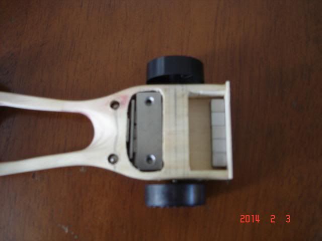
The first picture is the weight configuration I was planning to use. My understanding from reading other people comments is that for the best results I should have my weights as low as possible with as much weight in the back while still maintaining a COG of around 3/4 ~ 5/8 (which is what I have here). My assumption is by having as much weight as possible in the back, you get that little extra push coming off the down slope.
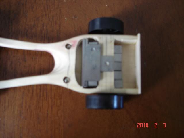
But according to Shawn, if you compress all your weights with in the diameter of your rear wheels as I have done in the picture below, you will have better results. (By the way, I was able to achieve the same COG this way as in the photo above.) This is the first time I've heard of this type of weight distribution and I'm just having a little trouble understanding how his method is better than the way I had it set up above. If anyone can explain his concept better, I would appreciate it.
I figured it would be easier to explain if I took some photos.
The first picture is the weight configuration I was planning to use. My understanding from reading other people comments is that for the best results I should have my weights as low as possible with as much weight in the back while still maintaining a COG of around 3/4 ~ 5/8 (which is what I have here). My assumption is by having as much weight as possible in the back, you get that little extra push coming off the down slope.
Yes, I also assume that once you're flat and level this advantage becomes neutral.Stan Pope wrote:Remember, too, that on the straight ramp of a Best Track moving the CM rearward does not give advantage. The advantage from more rearward location of the CM happens in the curved section, where you are reporting you're gaining advantage!

But according to Shawn, if you compress all your weights with in the diameter of your rear wheels as I have done in the picture below, you will have better results. (By the way, I was able to achieve the same COG this way as in the photo above.) This is the first time I've heard of this type of weight distribution and I'm just having a little trouble understanding how his method is better than the way I had it set up above. If anyone can explain his concept better, I would appreciate it.

Re: Weight Placement
Well, Black Fox, cut off all that wood behind the rear wheels and move it up front. That'll push your COG higher up the arc. Then put 2 rows of 6, 1/4" cubes behind the rear axle slot. You will have to remove some of that wood around the rear axle. There should be 5/8" of space behind the rear axle slot. Remove the front weights and put 2 rows of 1/4" cubes in front of the rear axle slot (12 cubes would be nice but I don't know what your car weighs) then that would be a good start. Might we see a picture of the whole car. Maybe more wood can be removed from other areas of the car so we can add more cubes. That's the way I would get started.
-
Stan Pope
- Pine Head Legend
- Posts: 6856
- Joined: Sat Jul 05, 2003 7:01 pm
- Location: Morton, Illinois
- Contact:
Re: Weight Placement
Except that I must guess at the actual number of cubes in each pocket! My guess is two rows of 5 stacked vertically in the rear pocket and a similar stack in the front pocket. Then some miscellaneous cast tungsten to bring the car up to 5 ounces.Black Fox wrote: Hi Stan
I figured it would be easier to explain if I took some photos.
More than that ... you gain no advantage prior to entering the curve!Black Fox wrote: The first picture is the weight configuration I was planning to use. My understanding from reading other people comments is that for the best results I should have my weights as low as possible with as much weight in the back while still maintaining a COG of around 3/4 ~ 5/8 (which is what I have here). My assumption is by having as much weight as possible in the back, you get that little extra push coming off the down slope.
Yes, I also assume that once you're flat and level this advantage becomes neutral.Stan Pope wrote:Remember, too, that on the straight ramp of a Best Track moving the CM rearward does not give advantage. The advantage from more rearward location of the CM happens in the curved section, where you are reporting you're gaining advantage!
Analysis can be a bit tricky, but if you chart the track, one or two inches at a time, and measure the CM height as the nose of each car reaches your "tick marks" you can see how much the CM drops for each interval of travel. If the drop is the same, neither gets an advantage. Once the cars enter the curve, that picture will change. The path followed by the car with the more centrally CM "flattens out" sooner. The result is that it's CM drops a bit less, and, consequently, gets less acceleration. The more rearward CM gets more acceleration and it gets it earlier!
That is the role of CM location.
Shawn's comments are aimed at getting just a bit extra out of your car. Just as it takes energy away from your top speed to make the wheels spin up, it also takes energy to change the car's orientation. It doesn't take a lot of energy, but it does take a bit. And that bit could have been speed had it not been used to change orientation. The amount of energy required depends on the moment of inertia of the whole car. In this case, measure the moment of inertia as the car "spins" about its CM. Now, the car's moment of inertia is a lot larger than that of the wheels, but the orientation change is only about 1/12 of a rotation and it happens over a longer time, so the difference in energy usage will not be a lot.
There is a trade-off, though. Stacking the rearmost 10 cubes two-deep (vertically) near the axle provides a lower moment of inertia than laying them flat, but is also costs in frontal cross section area. Now the car must be 1/2" thick rather than 1/4" thick. And that will add to the aerodynamic drag that the car will experience during its entire trip along the track. I'll leave it to you to decide which way to bend that trade-off.
Now, what about the cubes in the front pocket? If, as I stated above, the cost of rotating the car varies with the car's moment of inertia about its CM (not its rear axle) is true, then I would also try to center that front pocket weight about the car's CM! This is different from Shawn's statement ... not a lot different, but a different principle. Juggling the moment of inertia by moving the front pocket weights forward a bit while holding the CM location fixed will require moving the rear pocket weights backward, which may not be a beneficial trade-offs, too! Recall that a mass farther away from the center of rotation has more effect on the moment of inertia than the same mass close to the center of rotation.
HTH!
Stan
"If it's not for the boys, it's for the birds!"
"If it's not for the boys, it's for the birds!"
-
Shawn Stebleton
- Master Pine Head

- Posts: 190
- Joined: Wed Jan 25, 2012 7:20 pm
- Location: Monroeville, PA
Re: Weight Placement
Yes, Black Fox, the 2nd picture with the weights close together is similar to how I taught my boys to do it.
Also, Speedster is right. Cut off the extra wood in back (if allowed by your rules). We do that. We use a craft stick as a front wing, epoxied in (2-part 5-minute epoxy) for strength, instead of gluing back on the sawed off wood from the back. We have a brutal stop and the craft stick has more strength than regular pine.
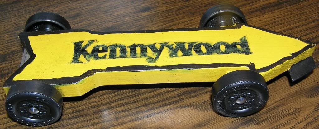
Here are pictures of my son's car this year:
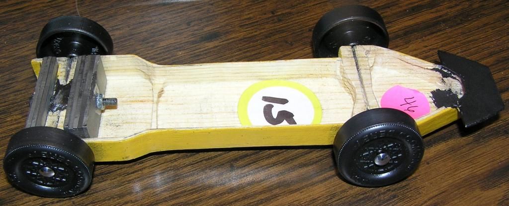
And a close-up of the weights:
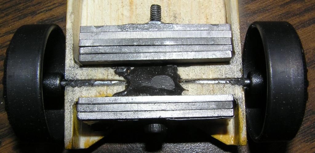
We used 8 tungsten plates from MaxV, but oriented in a vertical arrangement. In retiring an old laptop computer many years ago, I had saved the screws and nuts. They are size M3, about 30mm long. I had to drill out a very minimal amount of the hole in the center to get it to fit, but it worked fine. The tungsten was 4.03oz by itself. There are several pieces of lead golf tape stuck on the rear end of the weights for 0.07oz, and the weight of the screw and nut itself, also 0.07oz. The rear wheels and axles are 0.23oz. I don't know how much the wood and epoxy weigh, but they aren't 0.00. That's about 4.40oz in the space of the rear wheel. Yes, I know a small bit of the screw extends in front of that, but I'm using that to offset the weight of the wood and epoxy. The CoM is at the nut, which is at the front edge of the rear wheels. The lead tape at the back of the rearmost tungsten plate is just under 15/16" behind the CoM, which means that 4.14oz of the 5.00oz is rotating within less than one inch away from the CoM.
The car body is 5/8" thick at the point where the plates are. That accounts for the plates and the wood top (very very thin). It's minimally thicker than a car with 1/4" cubes with a car body on top of it. The cross-sectional increase is very small. Underbody clearance is 5/16". (No 3/8" requirement--it just had to fit the track in this regard.) The vertical placement of the CoM is just a small bit above the axle plane--about 1/8". Not too bad.
Explanation for the compact weight design:
Think of a see-saw with twins, one on each end, and one of them up while the other is down. How much force does it take to rotate it so that the other twin is up? Now have the twins move to the middle, and start with the board in the same position. Now how much force does it take to rotate it? The Pinewood Derby car rotates from the start to the flat and has to use energy to rotate. That energy comes from the only place it can--the potential energy the car started with. If you lose less energy during the rotation of the car, you have more left over for speed. By spreading the weight out, it takes more energy to rotate.
Note: This car was specifically designed for the old-style Best Track with the 2' radius curve. The rotation starts very quickly and abruptly, the rotation itself is fast, then it is immediately sent to the flat just as quick. I don't know if a car on an arc-curve track like our pack's Piantedosi Classic track would necessarily benefit from this type of design, but we had to design one car, as we could not change the car for the district race. Perhaps weights more spread out and lower would be better for the arc-curve. I don't know. I just know that the cars my son has made the last 4 years, using this weight design, came out of the transition with more speed than the competitors.
Also, Speedster is right. Cut off the extra wood in back (if allowed by your rules). We do that. We use a craft stick as a front wing, epoxied in (2-part 5-minute epoxy) for strength, instead of gluing back on the sawed off wood from the back. We have a brutal stop and the craft stick has more strength than regular pine.
Here are pictures of my son's car this year:


And a close-up of the weights:

We used 8 tungsten plates from MaxV, but oriented in a vertical arrangement. In retiring an old laptop computer many years ago, I had saved the screws and nuts. They are size M3, about 30mm long. I had to drill out a very minimal amount of the hole in the center to get it to fit, but it worked fine. The tungsten was 4.03oz by itself. There are several pieces of lead golf tape stuck on the rear end of the weights for 0.07oz, and the weight of the screw and nut itself, also 0.07oz. The rear wheels and axles are 0.23oz. I don't know how much the wood and epoxy weigh, but they aren't 0.00. That's about 4.40oz in the space of the rear wheel. Yes, I know a small bit of the screw extends in front of that, but I'm using that to offset the weight of the wood and epoxy. The CoM is at the nut, which is at the front edge of the rear wheels. The lead tape at the back of the rearmost tungsten plate is just under 15/16" behind the CoM, which means that 4.14oz of the 5.00oz is rotating within less than one inch away from the CoM.
The car body is 5/8" thick at the point where the plates are. That accounts for the plates and the wood top (very very thin). It's minimally thicker than a car with 1/4" cubes with a car body on top of it. The cross-sectional increase is very small. Underbody clearance is 5/16". (No 3/8" requirement--it just had to fit the track in this regard.) The vertical placement of the CoM is just a small bit above the axle plane--about 1/8". Not too bad.
Explanation for the compact weight design:
Think of a see-saw with twins, one on each end, and one of them up while the other is down. How much force does it take to rotate it so that the other twin is up? Now have the twins move to the middle, and start with the board in the same position. Now how much force does it take to rotate it? The Pinewood Derby car rotates from the start to the flat and has to use energy to rotate. That energy comes from the only place it can--the potential energy the car started with. If you lose less energy during the rotation of the car, you have more left over for speed. By spreading the weight out, it takes more energy to rotate.
Note: This car was specifically designed for the old-style Best Track with the 2' radius curve. The rotation starts very quickly and abruptly, the rotation itself is fast, then it is immediately sent to the flat just as quick. I don't know if a car on an arc-curve track like our pack's Piantedosi Classic track would necessarily benefit from this type of design, but we had to design one car, as we could not change the car for the district race. Perhaps weights more spread out and lower would be better for the arc-curve. I don't know. I just know that the cars my son has made the last 4 years, using this weight design, came out of the transition with more speed than the competitors.
Shawn
Re: Weight Placement
Hi Shawn
Okay now I understand. Interesting theory. Maybe this might be more advantageous on an aluminum track which generally have a sharper bend. I'll have to give this some thought. Also, never thought about shortening the back end too. Very interesting.
Okay now I understand. Interesting theory. Maybe this might be more advantageous on an aluminum track which generally have a sharper bend. I'll have to give this some thought. Also, never thought about shortening the back end too. Very interesting.
Re: Weight Placement
Shawn, that is clever. I think that is a good set up on any track.
The "Best" track is the only aluminum incline track with the quick curve as far as I know. The Freedom aluminum track has a circular arc like what is seen in the scout book. We race on the "Best" track first and then the Freedom track at our District races. Our cars always seem to do better on the Freedom track once we get by the "Best" track.
Do you think putting 1 1/2 ounces of weight behind the rear axle slot is better then putting 2 ounces behind and moving the rest of the weight a bit forward to get the COM? Seems I read someplace 1 1/2 ounces is actually recommended on a stock wheelbase car.
-
Shawn Stebleton
- Master Pine Head
- Posts: 190
- Joined: Wed Jan 25, 2012 7:20 pm
- Location: Monroeville, PA
Re: Weight Placement
Black Fox wrote:Maybe this might be more advantageous on an aluminum track which generally have a sharper bend.
There is a tradeoff between low CoM for increased potential energy, longitudinally compact CoM for retaining speed through the arc, and CoM offset to the DFW side for stability. They each have their own properties, and lend themselves to different styles of tracks. A large arc segment with a short flat may actually favor a higher CoM design.Shawn Stebleton wrote:Note: This car was specifically designed for the old-style Best Track with the 2' radius curve.
I would build for the sharpest arc the car would see, and the length of track.
Shawn
-
Shawn Stebleton
- Master Pine Head
- Posts: 190
- Joined: Wed Jan 25, 2012 7:20 pm
- Location: Monroeville, PA
Re: Weight Placement
By moving some weight back and other weight forward and keeping the same CoM position relative to the rear axle, you are making the "moment arm" longer. I think the moment arm length is based on the square of the distance of all the "pieces" of mass from the CoM. Yes, some is closer, but the ones that are further affect the moment arm much more.Speedster wrote:Do you think putting 1 1/2 ounces of weight behind the rear axle slot is better then putting 2 ounces behind and moving the rest of the weight a bit forward to get the COM? Seems I read someplace 1 1/2 ounces is actually recommended on a stock wheelbase car.
Let's say the "piece" at 3mm behind the CoM gets moved up to being at the CoM. The piece at 8mm gets moved back to 11mm to keep the same CoM. 3^2 + 8^2 = 9 + 64 = 75, whereas 0^2 + 11^2 = 0 + 121 = 121. The 75 represents a lower moment arm, and therefore less energy is needed to rotate it.
If I'm totally wrong about this, please correct me. I was not an engineering major.
Shawn
-
FatSebastian

- Pine Head Legend
- Posts: 2818
- Joined: Wed Jun 17, 2009 2:49 pm
- Location: Boogerton, PA
Re: Weight Placement
Is this a reference to Michael Lastufka's clever "Warp Field" hypothesis (discussed in this topic), or something else?Shawn Stebleton wrote:A large arc segment with a short flat may actually favor a higher CoM design.
-
Stan Pope
- Pine Head Legend
- Posts: 6856
- Joined: Sat Jul 05, 2003 7:01 pm
- Location: Morton, Illinois
- Contact:
Re: Weight Placement
Me neither. But, lets pretend that we were.Shawn Stebleton wrote:...
Let's say the "piece" at 3mm behind the CoM gets moved up to being at the CoM. The piece at 8mm gets moved back to 11mm to keep the same CoM. 3^2 + 8^2 = 9 + 64 = 75, whereas 0^2 + 11^2 = 0 + 121 = 121. The 75 represents a lower moment arm, and therefore less energy is needed to rotate it.
If I'm totally wrong about this, please correct me. I was not an engineering major.
If the masses at 3 and 8 are identical then your analysis is okay. The numbers are proportional to the energy required to move them at a specific angular velocity.
If the moves you describe do keep the CM at the same location, then masses are, indeed, equal.
But, if the two masses are not the same, the analysis is incomplete.
Stan
"If it's not for the boys, it's for the birds!"
"If it's not for the boys, it's for the birds!"
-
SlartyBartFast

- Master Pine Head
- Posts: 272
- Joined: Mon Feb 12, 2007 11:30 am
- Location: Montreal, Quebec
Re: Weight Placement
Here we go again, I come back from a long hiatus and get sucked in to thinking these things through and I start jumping in on threads (probably half-cocked).
I often wonder if these discussions are using terms in way that I am familiar and whether the armchair physicists have it right and my brain is addled or whether the nagging doubt in my head is correct.
Angular momentum, angular intertia, moment arms, etc, etc.
In the desire to define and justify everything so much seems to be simplified that I have a hard time putting my head around it.
As the car goes around the transition curve, there are two points around which it rotates. The rear axle as the nose lifts, and the centre of rotation which is probably somewhere off above the car. The center of rotation is dynamic and depends on the wheelbase and the track curve.
Given those two centres, although that's probably muddled as one is related to the other, the distance between the centres and the CM give you the inertias and momentums.
Of course, I might simply be rambling (see above about being half-cocked).
I often wonder if these discussions are using terms in way that I am familiar and whether the armchair physicists have it right and my brain is addled or whether the nagging doubt in my head is correct.
Angular momentum, angular intertia, moment arms, etc, etc.
In the desire to define and justify everything so much seems to be simplified that I have a hard time putting my head around it.
My muddled memory and the time since my last physics and dynamics class aside, the car most certainly does not spin around its CM.Stan Pope wrote:In this case, measure the moment of inertia as the car "spins" about its CM.
As the car goes around the transition curve, there are two points around which it rotates. The rear axle as the nose lifts, and the centre of rotation which is probably somewhere off above the car. The center of rotation is dynamic and depends on the wheelbase and the track curve.
Given those two centres, although that's probably muddled as one is related to the other, the distance between the centres and the CM give you the inertias and momentums.
Of course, I might simply be rambling (see above about being half-cocked).
-
Shawn Stebleton
- Master Pine Head
- Posts: 190
- Joined: Wed Jan 25, 2012 7:20 pm
- Location: Monroeville, PA
Re: Weight Placement
I was assuming the two masses are the same. Sorry if I did not mention that. I didn't know that they needed to be the same for the example I presented. I'm an "arm chair engineer" and have no experience in the matter. I'm just trying to understand and use the terms correctly and have learned more than I ever thought I would about engineering and physics on this website due to you guys. Many thanks.Stan Pope wrote:But, if the two masses are not the same, the analysis is incomplete.
So having the extra weight around the rear axle in a compact form may be good regarding one of the points of rotation? And that point is near the CoM? No idea about the other point of rotation, but adding the extra weight very close to two out of three ain't bad!SlartyBartFast wrote:....the car most certainly does not spin around its CM.
As the car goes around the transition curve, there are two points around which it rotates. The rear axle as the nose lifts, and the centre of rotation which is probably somewhere off above the car. The center of rotation is dynamic and depends on the wheelbase and the track curve.
Shawn
